There are three basic structural elements to designing a bridge: the beam, compression members, and tension members. The beam is a simple structure that may link one piece of land to another piece of land separated by a stream, river, or any body of water. When designing a beam bridge a sketch is made showing the elements in the problem which include the geometry and the forces acting on the beam. What must be considered is the anticipated traffic on the beam. Will it be pedestrian, vehicle, or both? This is important because it may dictate the materials used in the construction. Will the beam be made of wood, concrete, or steel? Also, what will be the supporting materials needed to hold the beam in place?
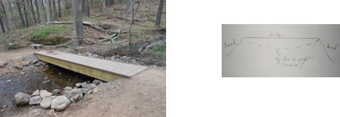
Figure 1: The above beam bridge is on a trail in a park in Branford, CT and is a cross over a small stream. The sketch shows a straight bridge between two land pieces. The dashed lines show that weight on the bridge will cause it to sag and with too much weight the bridge will collapse.
Traffic on the beam will cause it to buckle downward if it is too heavy. In this case, compression members are needed to counter it. We see many bridges with thick concrete pilings under them.
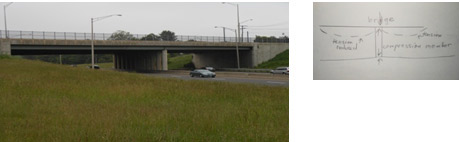
Figure 2: Pictured is a compression bridge on an interstate highway in Branford, CT. In the sketch, the arrows show where the compression forces act on the bridge. Compression is a pushing force. In this case, the concrete piling pushes down to the ground and the ground pushes up to the piling. Likewise, on the bridge, the two forces push against each other at the piling. Notice that the tension is halved.
If the bridge is long with anticipated frequent or heavy traffic tension members will be applied. These bridges will have cables pulling the beam upwards.
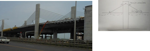
Figure 3: The sketch shows the tension forces acting on a bridge. Tension is a pulling force and the arrows show the forces pulling in opposite directions. The cables reduce the tension in half on both sides of the compression tower. Pictured is the Pearl Harbor Memorial Bridge in New Haven, CT showing some tension members. The bridge is not a pure tension bridge. It is a cross between a cable-stayed bridge and a girder bridge called an extradosed bridge.
If forces acting on a bridge, whether it be pedestrians or vehicles, are not balanced the tension or compression forces may become too great on one side to support the weight of the bridge and may collapse. So, it becomes important to assess where the stresses are and then spread the force over a greater area or transfer it to a stronger point on the bridge. This can be accomplished by using other designs as arches, trusses, or cables that can transfer compression and tension forces. As new materials become available new bridge designs become apparent and mathematical models are used to analyze and test them.
Now, let us look at what is involved in bridge design. First, there must be a concept–a bridge. But, what kind of bridge? Who will use the bridge-cars, trucks, pedestrians? What is the traffic flow and how heavy will it be? Will it be spanning over water or another highway? What is the economic feasibility of the bridge? What is the future projection for the bridge?
Next, a model needs to be designed and constructed maybe both or either a scale model or a design model using software. The design of the bridge will depend on its use. Will the bridge be a member bridge, a tension bridge, or a suspension bridge? Or, will a new design be introduced? The model needs to be analyzed and tested for strengths and weaknesses and the weaknesses corrected if possible. And, lastly, it needs to be determined if the design meets the objectives of its purpose.
Finally, an evaluation is performed and a decision made on whether to proceed, halt, or redesign the project. Engineers are involved from inception and throughout construction.