A system or device that converts heat into work is a heat engine. Heat engines are cyclic: some part of the system absorbs energy, work is done and the system returns to its original state in order for the cycle to begin again. Although the term “engine” might call to mind the complex device that powers an automobile, in thermodynamics a heat engine can be as simple as gas in a piston that expands as heat is added and contracts as the gas cools. There are also tiny molecular engines in living cells. Although they are much smaller than a piston or the engine in a car, these tiny engines perform the same function, transforming energy into motion.
We can describe heat engines of all kinds by a simple generic model. The engine is thermally connected to a reservoir of higher (hotter) temperature (T
h
) and to a reservoir of lower (cooler) temperature (T
c
). A reservoir is a part of a system large enough either to absorb or supply heat without a change in temperature. In an old-time steam engine, for example, the furnace serves as the hot reservoir and the surrounding atmosphere acts as the cold reservoir. Energy Q
h
flows from the hot reservoir into the engine; during this process some of the energy goes into work W, and the remainder Q
c
flows out of the engine and into the cold reservoir in the form of heat.
A perfect engine would be one in which all of the energy Q
h
taken in from the hot reservoir is converted to work, with no heat at all going into the cold reservoir (that is, Q
c
=0 ). This would be 100% efficient engine: None of the energy from the hot reservoir would be “thrown away” to the cold reservoir. Unfortunately, the second law of thermodynamic stipulates that such a perfect engine is impossible. To understand why, note that there is an increase in order of the hot reservoir because energy flows out of this reservoir and therefore some of the molecules of the reservoir must decrease their random motion and so become more orderly. This corresponds to a decrease in entropy, which is not allowed in an isolated system.
The conclusion is that we simply cannot build a perfect engine that is 100% efficient. The
Kelvin-Planck
statement is a rewording of the second law of thermodynamics that describes the inherent efficiency limits of heat engines:
No process is possible in which heat is absorbed from a reservoir and converted completely into work.
In order for a heat engine to satisfy the second law of thermodynamics, some heat must flow into the cold reservoir in order to make the cold reservoir less ordered. This happens because the energy added to the cold reservoir increases the random motion of the reservoir’s molecules. This corresponds to an increase in entropy that offsets the decrease in entropy in the hot reservoir.
In the early stages of the industrial revolution, most of the energy needed to run mills and factories came from water power. Water in a high reservoir will naturally flow downhill. A waterwheel can be used to harness this natural flow of water to produce useful energy because some of the potential energy lost by the water as it flows downhill can be converted into other forms such as electricity.
It is possible to do something similar with heat. Thermal energy is naturally transferred from a hot reservoir to a cold reservoir; it is possible to take some of this energy as it is transferred and convert it to other forms. This is the job of a heat engine as described above.
As stated above, no heat engine can operate without exhausting some fraction of the heat into a cold reservoir. This is not a limitation on our engineering abilities. It is a fundamental law of nature.
The maximum possible efficiency of a heat engine is determined by the second law of thermodynamics. We will not perform a detailed derivation, but simply note that the second law gives the maximum efficiency of a heat engine as e
max
= 1 – T
c
/T
h
It is seen that the efficiency is 0 when T
c
= T
h
, and it is 1 when T
c
= 0 (absolute zero). The maximum efficiency of any heat engine is therefore determined by the ratio of the temperatures of the hot and cold reservoirs. It is possible to increase the efficiency of a heat engine by increasing the temperature of the hot reservoir and/or decreasing the temperature of the cold reservoir. The efficiency of the above equation is also called the
Carnot
efficiency, after a theoretical heat engine that achieves this maximum possible efficiency. The actual efficiency of real heat engines is usually about 10% to 50% than the theoretical maximum.
A Stirling engine is a heat engine that operates by cyclic compression and expansion of air or other gas (the working fluid) at different temperatures, such that there is a net conversion of heat energy to mechanical work. More specifically, the Stirling engine is a closed-cycle regenerative heat engine with a permanently gaseous working fluid. “Closed-cycle” refers to a thermodynamic system in which the working fluid is permanently contained and recycled within the system. The term “regenerative” describes the use of a specific type of internal heat exchanger and “thermal store”, known as the regenerator. The inclusion of a regenerator differentiates the Stirling engine from other closed cycle hot air engines.
The Stirling engine was invented and patented by Robert Stirling in 1816.
It followed earlier attempts to build an air engine but was probably the first put to practical use when, in 1818, an engine built by Stirling was employed pumping water in a quarry. The main subject of Stirling's original patent was a heat exchanger, which he called an “economizer” for its enhancement of fuel economy in a variety of applications. The patent also described in detail the employment of one form of the economiser in his unique closed-cycle air engine design in which application it is now generally known as a “regenerator”. Subsequent development by Robert Stirling and his brother James, an engineer, resulted in patents for various improved configurations of the original engine including pressurization, which by 1843, had sufficiently increased power output to drive all the machinery at a Dundee cast iron factory, in Scotland.
In addition to saving fuel, the inventors were motivated to create a safer alternative to the steam engines, whose boilers frequently exploded, causing many injuries and fatalities.
Although the Stirling engine was conceived in 1816 as an industrial machine to rival the steam engine, its practical use was largely confined to low-power domestic applications for over a century.
Stirling engines have a high efficiency compared to steam engines, being able to reach 50% efficiency. They are also capable of quiet operation and can use almost any heat source. The heat energy source is generated external to the Stirling engine rather than by internal combustion as with the Otto cycle (used in gasoline engines) or Diesel cycle engines.
Because the Stirling engine is compatible with alternative and renewable energy sources it could become increasingly significant as the price of conventional fuels rises, and also in light of concerns such as depletion of oil supplies and climate change. This type of engine is currently generating interest as the core component of micro combined heat and power (CHP) units, in which it is more efficient and safer than a comparable steam engine. However, it has a low power-to-weight ratio, rendering it more suitable for use in static installations where space and weight are not factors of primary importance.
How does the Stirling eng
i
ne work?
The engine is designed so that the working gas is compressed in the colder portion of the engine and expanded in the hotter portion resulting in a net conversion of heat into work. An internal regenerative heat exchanger increases the Stirling engine’s thermal efficiency compared to simpler hot air engines lacking this feature.
As a consequence of closed cycle operation, the heat driving a Stirling engine must be transmitted from a heat source to the working fluid by heat exchangers and finally to a heat sink. A Stirling engine system has at least one heat source, one heat sink and up to five heat exchangers. Some types may combine or dispense with some of these
The heat source may be provided by the combustion of a fuel and, since the combustion products do not mix with the working fluid and therefore do not come into contact with the internal parts of the engine, a Stirling engine can run on fuels that would damage other engines internal parts.
Other suitable heat sources include concentrated solar energy, geothermal energy, nuclear energy, waste heat and bioenergy. If solar power is used as a heat source, regular solar mirrors and solar dishes may be utilized, a good example in this direction being the point focus parabolic mirror with Stirling engine at its center at Plataforma Solar de Almería (PSA) in Spain. (See the image below)
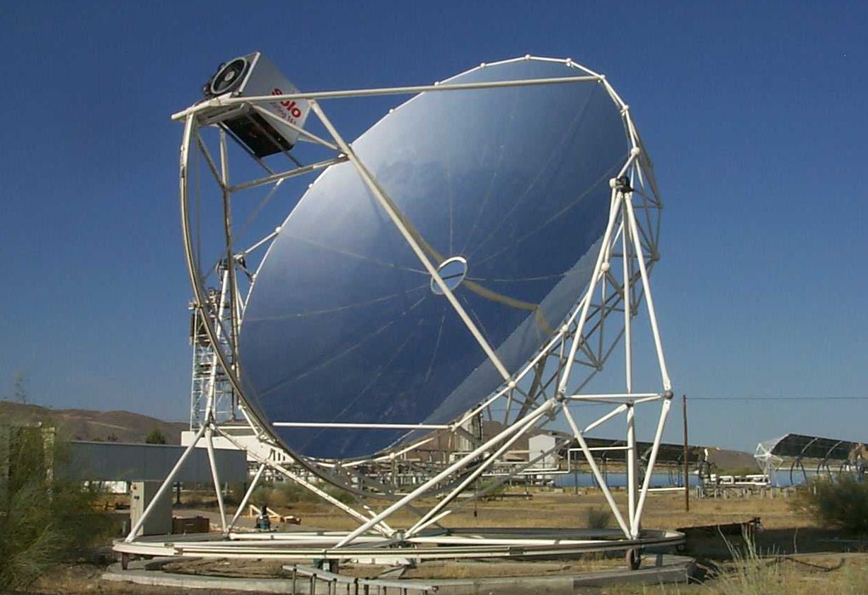
(Source: http://ifisc.uib-csic.es/raul/CURSOS/TERMO/Stirling%20engine.pdf )
The use of Fresnel lenses and mirrors has also been advocated, for example in planetary surface exploration.
In a Stirling engine, the regenerator is an internal heat exchanger and temporary heat store placed between the hot and cold spaces such that the working fluid passes through it first in one direction then the other, taking heat from the fluid in one direction, and returning it in the other. It can be as simple as metal mesh or foam, and benefits from high surface area, high heat capacity, low conductivity and low flow friction. Its function is to retain within the system that heat that would otherwise be lost to the environment at temperatures intermediate to the maximum and minimum cycle temperature, thus enabling the thermal efficiency of the cycle (though not of any practical engine) to approach the limiting Carnot efficiency.
The primary effect of regeneration in a Stirling engine is to increase the thermal efficiency by recycling internal heat that would otherwise pass through the engine. As a secondary effect, increased thermal efficiency yields a higher power output from a given set of hot and cold heat exchangers. These usually limit the engine’s heat throughput. In practice this additional power may not be fully realized as the additional “dead space” (unswept volume) and pumping loss inherent in practical regenerators reduces the potential efficiency gains from regeneration.
The design challenge for a Stirling engine regenerator is to provide sufficient heat transfer capacity without introducing too much additional internal volume (“dead space”) or flow resistance. These inherent design conflicts are one of many factors that limit the efficiency of practical Stirling engines.
The regenerator is the key component invented by Stirling and its presence distinguishes a true Stirling engine from any other closed cycle hot air engine. Many small “toy” Stirling engines, particularly low-temperature difference (LTD) types, do not have a distinct regenerator component and might be considered hot air engines; however a small amount of regeneration is provided by the surface of the displacer itself and the nearby cylinder wall, or similarly the passage connecting the hot and cold cylinders of an alpha configuration engine.